HP-32E Advanced Scientific Calculator
Recently got this machine from a local seller.
Like many of these kind of machines, this one also has corroded battery terminals caused by the Ni-Cd batteries forgotten inside the machine for years.
Although when I applied an external 3-Volt power supply i got a satisfying normal initialization showing "0.0000" in the LED display.
Tried the self test and nothing happened. The Enter key is not working at all.
Still I decided to buy it and see if I can repair it.
These pictures are from the seller advert.
This model would not be sold in a hard case like this one. Most probably the original owner, who owned several HP different models during his professional life, have sold the machine and kept the hard case for this one. Who knows.

The guilty component.

After opening the machine I found the missing battery connector lose inside.
One good thing: The machine was never opened before, although someone may have tried to undo the two screws a little but quit after realizing that it was "impossible" to open it without breaking it.
That frustrated tentative have left two marks on the two plastic threaded posts where the two screws goes. One post is cracked in three places but can easily be repaired.

And the usual look after a battery leak.
I was lucky because after cleaning all the battery leakage components I found out that the power supply flat cable didn't suffer enough corrosion to break.

The third IC is not installed. Some reports I have been reading mention that some 32E machines came with the middle position filled in.
1MA4-0003 DIP40 processor
1MA3-0004 DIP8 memory
1MA1-0009 DIP8 memory


General parts after cleaning.

Power supply.


Display and solder-less sandwiched PCA.
Component side.

Keyboard side.


The keyboard uses three plastic layers:
- Top layer – Five conductive trace lines with embedded clickable dome contacts and double paths for redundancy.
- Middle layer – Isolates top from bottom conductive trace lines
- Bottom layer – Part of the flex PCB with seven conductive trace lines with fixed base dome contacts and five additional trace lines to interconnect (via solder joints) with the five lines from the top layer.
The flex PCB is folded around a rigid metal/foam frame where one side support the keyboard and the other receives the IC’s and power supply interconnection using a solder-less sandwich approach.


Partial schematics.

I have used a ohmmeter to check continuity of some of the working keys.
A good contact gives zero Ohm.
The inoperative ENTER key was giving infinity resistance.
Initially I was afraid that the trace lines were broken because the ENTER key is not in series with any other key in the top layer flex PCB.
But then HP have designed the circuit with full redundancy paths, so the probable cause would be something else.
And after lifting the top layer flex PCB I saw the cause: the base contact at the bottom flex PCB was heavily oxidized at the point of contact of the upper metal contact embedded in the plastic dome.
After cleaning it the good continuity was restored.

Next steps involves the battery compartment connectors repair, fixing the plastic posts, and then start the reassembling for testing.
The battery connectors must be replaced with custom made ones.
Soldering is not a good idea as it will isolate the connection to the flat cable traces. However that's what I have done to be able to test the calculator. Of course after all this heat I got an isolated connector with about 18 Ohm resistance. So I have used an old trick on these cases: have soldered a thin wire between the battery connector and the flat cable copper trace.
Power supply back in its place in the plastic frame.
IC's lay down having pin1 pointing to the power supply.


Now it is the flex PCB assembly turn.
The brackets are prepared to be inserted on both sides.

A small detail concerning grounding.
This design uses positive common ground circuit.
Once the right side bracket is inserted (having the keyboard facing up), when the power switch is ON the battery positive side is connected to the metal frame.


And at last the big moment.
I used a set of two depleted 1.5V AA depleted batteries for the initial test for a total of around 2.5V when loaded.
In order to be able to test the PCA out of the case, I had to solder three thin wires to bypass the power switch. Use wrapping wire AWG33 or above. The thinner the better. And a low melting point solder is essential here. Just adjust your soldering station to an adequate temperature. Too low and the flex PCB will be destroyed as it will require more time to solder.
For this job I gave used a regular Antex CS18 18Watt thin tip soldering iron.
This is a simple procedure but requires special attention when soldering the wires because the flex plastic material is extremely fragile and have a low melting point.
Therefore tinning of the flex traces is not recommended. Just tin the thin wires and then while heating the wire just press it briefly (less than a second) against the flex traces using the soldering iron tip.
Clean and easy task.

After a couple of minutes, I got the battery low indicator.
At the time the batteries had 2.30V.

Initial current consumption of 103mA after power on.

The self test (STO followed by ENTER) passed without errors on every check I have done.
All LED display segments lit resulted in around 202mA.


I will leave the battery connectors fix for another time.
For now the calculator will be assembled having one battery connector soldered.
A small parenthesis to comment on the nice injection molded keys.
They don't make it like this anymore.


Details of the power switch.

Keys deposited in the front case frame.

And the PCA inserted into the front case.
Besides being a solderless design, this calculator is screwless design too (well, it uses just two screws to close the back cover.


Detail of the back cover latch at the front side.
This latch is the responsible for the notorious hard/delicate (chose your option) operation required to open this calculator.

The original battery was cleaned to remove all the leaked electrolytes and was inserted to make sure the soldered battery connector is mechanically functional.
I have ordered a set of new batteries with solder tags from TAS. Then a small surgery will be required to replace the old with the new ones. Waiting for arrival now.
Just for fun, tried to get SQRT(-2). Got an Error 0.

And again the self test passing with flying colors.


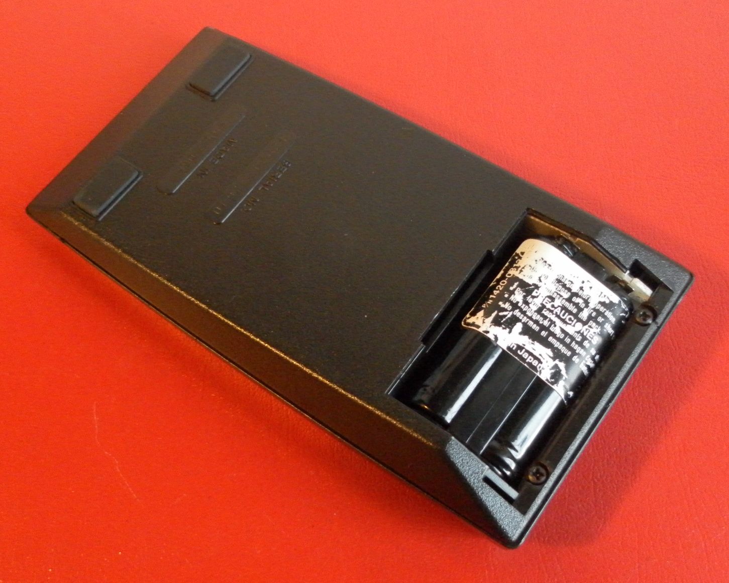
The AC battery charger i got with this machine has the p/n 82090B.
The battery that came with this machine has the p/n 1420-0813, Made in Japan.


Pouch.
Is it black or dark brown?
It depends on the light condition...


I received a new set of batteries and it are now installed in the battery compartment.
Instead of the original Ni-Cd based technology, I have used the Texcus Ni-MH type Mignon AA HR6 1.2Volt 2100mAh with solder tags.
I have soldered the tags on one side to set the two cells in series and have removed the tags on the other side facing the battery connector clips.
Because these batteries are a bit longer than the original ones, there is no need to use the original plastic frame that would add at least 1mm to the overall length.
The battery cover fits nicely as these battery diameter is the same as the original battery pack.

These batteries are sold with near full charge, so I set the calculator in test mode to have all segments lit and left the machine powered on.
Seven hours later it is operating normally with no sign of battery low annunciator.
Probably these batteries can give a maximum continuous operation for around 10 hours (2100mAh Ni-MH capacity / 200mA consumption with all digits lit).
According to the HP owners guide, the original battery pack would run for around 3 hours of continuous operation.
A quick calculation shows that that claim is correct (700mAh Ni-Cd capacity / 200mA = 3,5hours).

Self test procedure video:
Sem comentários:
Enviar um comentário