Texas SR-52 calculator 41'th anniversary in 2016
Great vintage machine.
As usual, battery leaking have corroded the PCA and the machine is faulty.


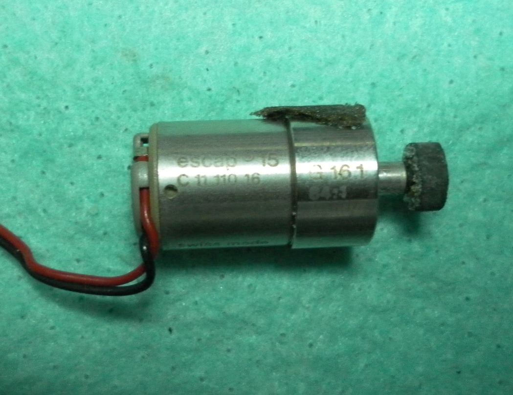
Card Reader motor.
Texas used a Swiss made precision motor and gearbox!
Model: escap 15
Ref: C 11 110 16
Date code: 1 76 (Jan-1976)
Gearbox Ref.: G 16.1 84:1


Motor schematic drawing.
Dimensions in mm.

Power supply voltages are within the tolerance interval.
Vdd = -10V; Vgg = -16V
OK.
Time for a deep dismantling here.
Keyboard removal.
Found two corroded wires of the "flat cable" assembly, and one third broke when removing it.
These corroded wires are the most difficult to desolder, as the iron heat is not easily transfered to the joint to melt it the required in short time. The longer the iron stays on the joint, thw more damage will result to the copper traces and components.


These vintage Siemens electrolytic capacitors are of the best quality at the time.
All of them are fine. And all made between 7602 and 7604 (1976 week 02 and 04).

Time for IC's extraction.
The task is easy although laborious and delicate.
This time I had to extract the chips without destroying them and keep the PCB copper pads in good shape fro the next chip insertion, only because I do not have spares and I need to reuse the chips.
Otherwise I would just cut out the chips and desolder the legs remains from the PCB.
So each one took me about 5 minutes to extract. As I said, this is a delicate job, considering the vintage state of the PCB and its, let us say, average quality.

The two piggyback RAM chips looks a little supicious.
One leg is missing there.
That's why I need the service guide (or another SR-52 to compare with).

The large SCOM and ARITH chips are easier to extract.
A very old dog trick from the 70's when we had to extract the chips to be tested of circuit:
After desoldering the pad, use a screwdriver to rock the chip legs until they get loose in the pad hole.
In this way the chip comes out easily.


I decided to extract the card reader controlller as well.

Partial dismantling.
I left the power supply oscillator and the 4 NAND chip in the circuit, as they don't seems to be related to this calculator problem.

Next step:
I found a couple of solder joints with marks of battery corrosion, so the new soldering will fix it.
And I'm planing to install DIP sockets and see if the extracted chips can work in this way.
The issue here is that the chips legs were cut off at the manufacturing plant and I have to check if they can be used in a socket.
Keyboard dismantling.
I saw some marks of corrosion at one of the edges of the KB PCB.
Removing the adhesive plastic film revealed the PCB routes.


It as an opportunity to draw the KB schematics, by using direct observation and with the help of an ohmmeter to check the connections.
The circuit traces presents about 90 Ohm per cm. The longer circuit traces measured more than 1KOhm.

After some head scratching trying to make sense of the above circuit, finally the Texas design was revealed
The KB matrix uses 6 Rows per 10 Columns for a total of 60 keys, where 45 key actually were used.

PCB was cleaned and the IC's reinserted to their original positions.
All resistors, capacitors, diodes, transistors and coils were tested good, with exception of the battery charging limiter resistor, that doesn't contribute to the current calculator fault.
This limiting resistor has signals of past overheating and its value is way out of the tolerance.
It is marked Brown/Orange/Black /Gold (13Ohm 5%) at 1/2W, and the current value is 17.2Ohm.
Despite its value is not that critical, it must be stable. So I replaced it with a 15Ohm that I had at hand.

Details of the Card Reader photocoupler sensor.
Contrary to the so many bad critics found in the forums on this card reader system (which I respect) I like its simplicity and easy of access.
I'm not saying it will be easy to replace the motor roller wheel, though.
That is the weak part of this design imho. The roller pressure is not adjustable as we find on the HP card readers and this alone creates a huge issue when restoring this mechanism.
So the photocoupler is a classic diode / photo-transistor combo.
Both are in good condition.
The photo-transistor presents about 56KOhm under fluorescent light and about 190KOhm in the dark.


7-segment LED 14-digits display details.
Printed labels: "UNIV SR" "EL SALVADOR 7551" "234 G"
The date code suggested it was made in 1975 week 51.


Reassembling the keyboard PCA takes a stady hand and lots of patience.
I had to remove the metal domes from the auto adhesive original plastic film.
Then put the domes, one row at a time, on the PCA.
To fix them in place, I have just use a regular (1.5cm wide) transparent adhesive tape.
After having all the 5 rows with the domes in place, have cut the tape around the lateral sides and applied a second layer of a wider (5cm) adhesive tape to seal the keyboard contacts.
A brief electrical test confirmed that all rows and columns were isolated between them.
Testing a couple of key presses confirmed good electrical contact as well.

And then some more testing.
I'm using an external regulated power supply at 3.7V.
The initial random issues are gone, probably due to the cleaning and re-soldering.
After powering on from a cold state, this is what the SR52 can correctly calculate:
- All single X register functions (lnX, logX, x!, 1/x, √x, x2, sin, cos, tan, asin, acos, atan);
- D.MS and D/R both ways (using INV key);
- Degrees and Radians switch afects the calculations accordingly;
- P/R both works as well, because it takes Memory Register 00 in addition to Register X;
- The four basic arithmetic operations are fine when using the PROD (x and /) and SUM (+ and -) functions for direct register arithmetic on anyone of the Memory Registers 00-19.
- Storing and recalling numbers to Memory Registers 00 to 19 and 98 and 99.
However, two issues remains to be fixed:
1.- The machine stops responding to keystrokes about 15 minutes after power on.
2.- After powering on from cold, this is what the SR52 is failing to do:
- All operations requiring more than the single X register (˟√y, y˟ , x, /, +, -);
- In LRN mode (programming), any key-codes appears as "00";
- Trying to store numbers in the Memory Registers 60 and 70 will just recall "00" as well.
The usual forensics test: 9 sin cos tan atan acos asin returned: 9.000004661
This seems to be OK.


69! looks good too.

Idle current consumption around 160mA @ 3.7V.

Degrees selected. 45 sin looks to be OK.
(I also tried sin (Pi/2) in Radians mode and the result was 1)

Sem comentários:
Enviar um comentário