sexta-feira, 6 de maio de 2016

Canon Palmtronic F-6 scientific calculator from 1975

This machine uses a green Vacuum Fluorescent Display with 12 x 7-segment digits.
Two digits are reserved for minus signals and memory in use annunciation.
Another two digits are used for exponent.
This leaves 8 digits for mantissa.

After power on, the calculator shows a "0.^00".


2^5 (a^x) produces a good enough result: 31.999974^00


The usual forensic check gives this result: 12.199423^00
(Degrees mode. 9 sin cos tan tan^1 cos^1 sin^1)


Trying 1000 ln followed by e^x result in: 999.99964^00 


And the classic 1 / 3 followed by * 3 gives a result of: 0.9999999^00
A honest result from this 1975 calculator.


Pi internal constant stored value of: 3.1415926^00


 Clearing the calculator and doing e^x twice results in: 2.7182804^00


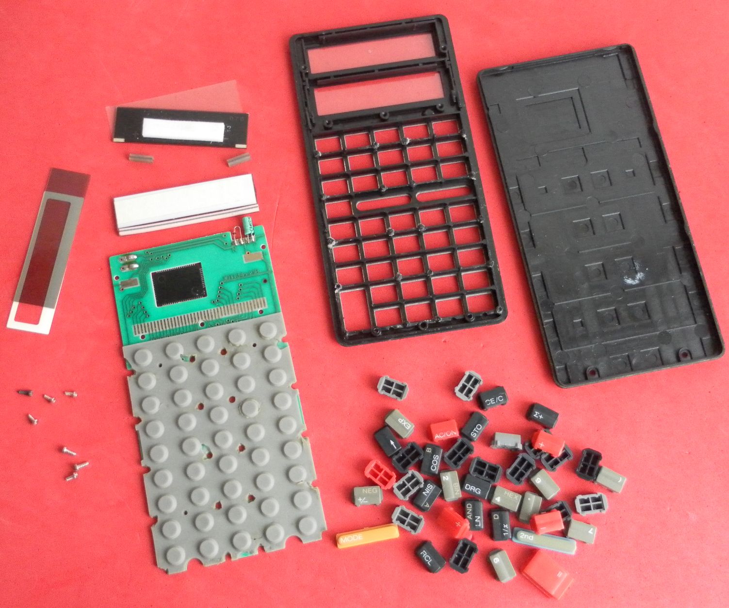
A singl screw holds the back cover. Solid case build.


Injection molded keys.


Shielding spring connector detail.
It connects the metal front plate to the machine PCB ground.
 

The Hitachi HD3699 SoC processor is complemented by a DC-DC power supply converter to generate the required high voltage to illuminate the VFD.  
The PCA set includes:
- The Processor/Power Supply/VFD main PCB, which in turn holds the Power Supply PCB.
- The Keyboard PCB.
All the three PCB's are soldered to each other by using single core wiring.

I measured the current consumption using a 4.5V power supply.
After power: 60mA
All digits on: 82mA

Calculating sin: 65mA.
This translates to a power consumption of a minimum of 270mW and a maximum of  370mW, much less than the declared 0.6W value in the back cover label (my calculator misses this label).


The VFD terminals are clearly identified.
Terminals "1" to "12" for the digits selection, then "a" to "g" and "dp" for the 7-segments plus decimal point selectors.

The electrolytic capacitors have a working voltage of 50V. I didn't care to check them s the machine works flawlessly with a bright steady VFD light emission..
From the two power supply transistors one one is identified, as D467 (2SD467 NPN Si).
The TDK transformer has a code of CD-1015, Japan.

The date codes in the transitor and in the SoC processor is "5L", so the year 1975 looks to be credible (I don't recall now the Japanese letters for month coding).

Visible in the picture is one broken black plastic pin that I couldn't find its original place.
this machine was opened before by others, bit apparently nothing was modified or repaired as all components terminal solder joints looks untouched. 


The 12 digit VFD is soldered to the Processor PCB.


quinta-feira, 5 de maio de 2016

Casio fx-3800P scientific pocket calculator

Made in mid 80's.
No way to know for sure as there are no date codes in any internal component.

Forensics result as displayed: 9.000015718
(Degrees mode. 9 sin cos tan atan acos asin)
I didn't try to get the extra digits, hence the different value from the rskey reported value.


Enter BaseN Hex mode. Get 2's complement of FFFF
Result: FFFF0001


Go to BaseN Dec mode.
Result: -65535


Low profile pocket machine typical of Casio of that era.
 

Single 3V CR2025 battery cell. 
 Undo the six steel screws to remove the back cover.


Back label:
Casio fx-3800P
DC 3VDC 0.0005W
Use Battery 3Vx1
Made in Japan
Casio Computer, Ltd.


The On-Off switch will get lose after removing the back cover and should be stored for later reassembly. 
Undo two extra screws to remove the PCA.
The LCD display assembly is attached to the PCB and it is not glued to the front panel. It is maintained in place by a foam that is pressed by the back cover.

One interesting note on the LCD assembly: The LCD itself is glued to a heavy metal frame. Not sure what was the engineering reasons behind this design choice. Most probably to give extra rigidity and protection, while giving the calculator more mass/weight for a more customer satisfying experience ?


No date codes on any component.
No identification in the SoC processor either.
The PCB reference is: G937-1 3


Only two passive components can be identified.
One SMD resistor marked as "224" (220000‎Ω = 220K‎Ω).
One legacy pass through tantalum polarized capacitor marked as "J335" (3300000pF = 3.3μF) 


quarta-feira, 4 de maio de 2016

Texas TI-34 solar scientific calculator

 Nice calculator powered by a single power source based on a four elements solar panel.
This one was made in 1987, November.

This machine was heavily used and abused, showing dents and marks all over the place, and heavy paint worn on the metallic front panel.
It was even opened and the PCB removed by destroying the plastic rivets and later fixed back with cyanolit glue that have also stuck the keyboard membrane to the PCB because the glue leaked thru the PCB holes.

But still works fine after all these years and misuse.


Forensics result: 8.999998637 
(9 sin cos tan atan acos asin)


Mode Hex: NOT(FFFF) = FFFFFF0000
Mode Dec = -65536


Back cover label:
Texas Instruments
I-1187
Assembled in taiwan
R.O.C.


The PCB is fixed by plastic rivets in the keyboard area, and screws in the processor/display/solar panel area.


 SoC processor: Toshiba T7988  8740H Japan
PCB ref. 10TI34-21B


Power supply regulator: a 1.75V LED and a 22uF capacitor in parallel with the 2.2V solar panel.


LCD display. Zebra strip used to connect it to the PCB.


Four elements 2.2V solar panel from National. Two zebra strips used to connect it to the PCB.


Power supply.
The solar panel generates 2.2V unloaded (off-circuit)  under strong light, and 1.75V under load (in-circuit), due to the tiny axial 1.75V LED installed in parallel.
The 22uF capacitor gives about 10 to 20 seconds memory contents retention under zero light conditions.


The tiny axial 1.75V LED can be seen here being tested off-circuit.